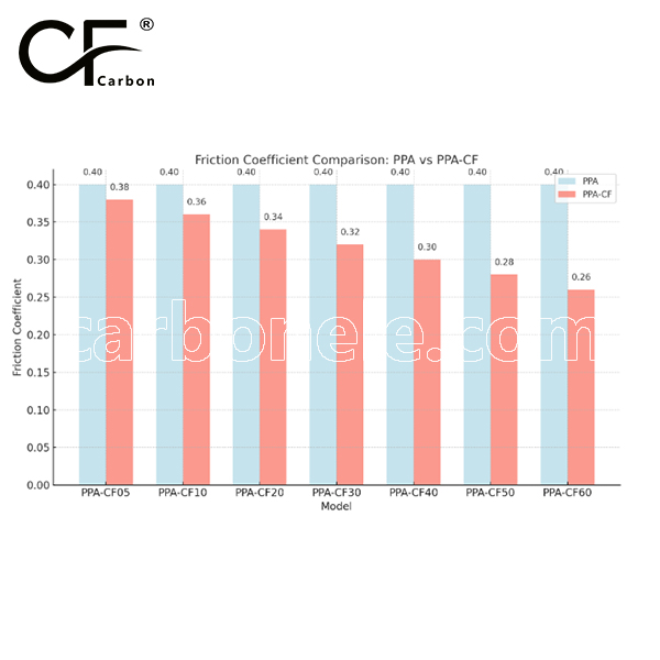
PEEK has a friction coefficient of 0.3 to 0.45, while PEEK-CF (carbon fiber reinforced) has a lower friction coefficient of 0.2 to 0.35, offering better wear resistance and reduced friction.


Fiber Pull‑out Risk: How Bonding in PEEK-CF10 Prevents Failure
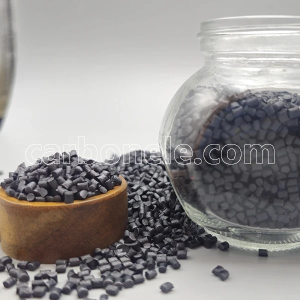
PEEK‑CF10 eliminates fiber pull‑out to keep composite parts intact. Discover its superior bonding, heat and chemical resistance, and light weight for high‑reliability designs.
- Model number: PEEK-CF-BCA1
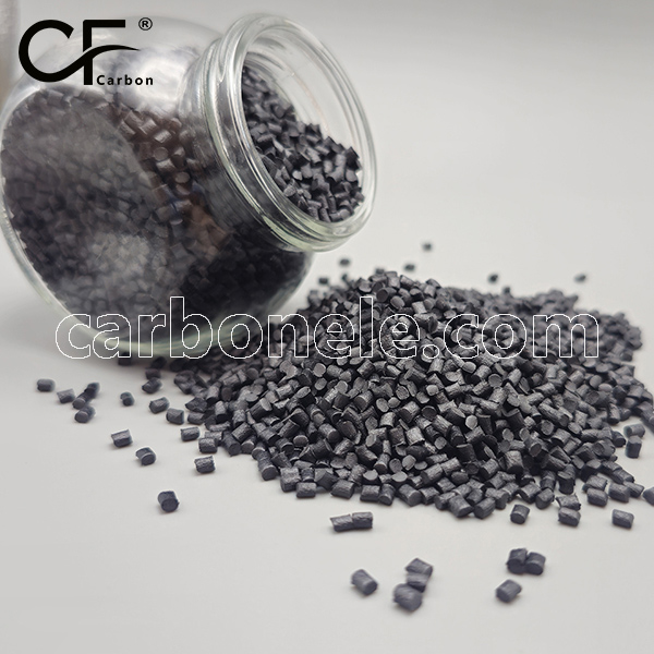
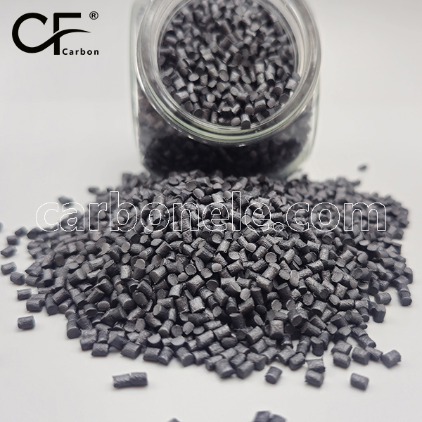
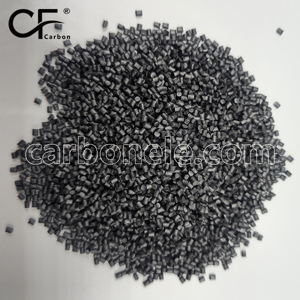
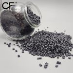
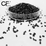
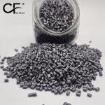
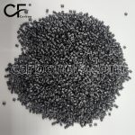
- Matrix Resin: Polyetheretherketone (PEEK)
- Reinforcing Filler: Carbon fiber
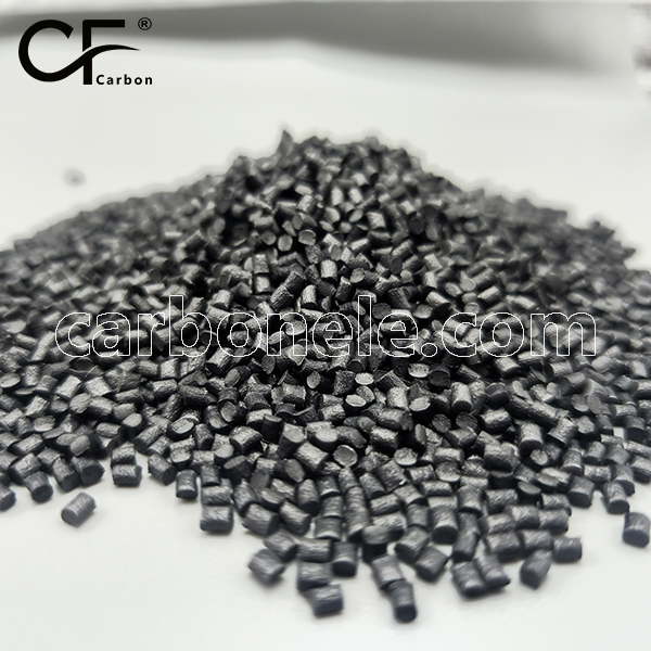
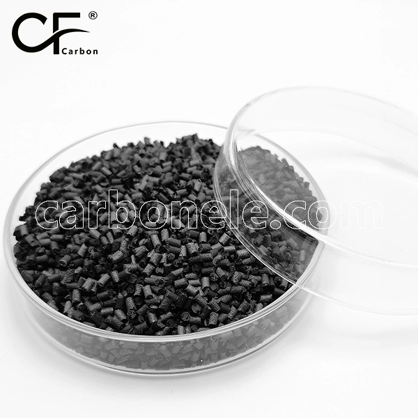
- Appearance: Granules
- Grade: Injection/extrusion grade
- Packaging: 25kgs/bag
Fiber Pull‑out Risk: How Bonding in PEEK-CF10 Prevents Failure
Why Fiber Pull‑out Threatens Composite Parts
Fiber pull‑out happens when reinforcing strands begin to slip away from the surrounding resin. What looks like a solid composite becomes a bundle of tiny cavities that invite cracking and surface erosion. For precision components a hidden weakness like this can end production runs without warning. A single dislodged filament may travel along a stress path and open a hairline split that keeps growing until the part shatters.
The true danger is that inspection often misses the earliest stages because the fibers retreat beneath the skin of the part. Operators notice the issue only when dimensions drift or when a mounting boss crumbles under load. Choosing a material that blocks fiber pull‑out at the source is therefore the safest route for engineers who refuse unplanned downtime.
The Bonding Advantage Built into PEEK‑CF10
PEEK‑CF10 solves the problem by creating a chemical handshake between its carbon reinforcement and its aromatic polymer backbone. Each carbon strand carries graphitic planes that welcome the high surface energy of molten PEEK‑CF10. During processing the resin flows around every filament and fills micro grooves that other plastics leave empty. When the melt cools it locks those grooves in place so firmly that the fiber can no longer slip. Instead of treating adhesives or coupling agents as a crutch PEEK‑CF10 makes the fiber and matrix behave like a single continuous solid.
While many composites depend on heavy fiber loadings to hit stiffness goals PEEK‑CF10 achieves high mechanical integrity with a balanced ten percent infusion. That leaves more room for flow paths and reduces part weight without compromising reliability. The result is a material that feels lighter in the hand yet stands firm when challenged by shock, heat, or aggressive cleaning solutions.
Application Example Carbon Composite Drone Bracket
Picture a lightweight drone that carries a high resolution camera for bridge inspection. Until recently the mounting bracket that joins the gimbal to the carbon boom was machined from aluminum. It worked but added weight that cut battery life and forced the flight controller to fight inertia during quick maneuvers. A switch to an unfilled engineering plastic removed weight yet introduced a new headache. After repeated flights the bracket developed fine cracks where the arms clamped the boom. Close analysis revealed fiber pull‑out around the screw holes that let vibration travel unchecked.
Engineers replaced the bracket with a version molded in PEEK‑CF10. The new part arrived almost half the weight of the metal original but kept its shape when the drone dove, rolled, and braked hard against gusty wind. Inspection after hundreds of launch cycles found no sign of delamination. The bracket’s carbon strands stayed buried inside the resin wall, sharing every impact and sending no micro cracks outward. Pilots reported longer flight times, steadier footage, and fewer maintenance checks. A small change of material delivered a big boost to operational productivity.
Design Guidelines for Drone Bracket Success
Use generous fillets at the base of each arm to spread bending loads. Keep gate placement near areas that demand fiber orientation along the load path. Add textured ribs rather than sharp ridges so PEEK‑CF10 can fill completely without trapping cold knit lines. Finally avoid over tightening screws during assembly; PEEK‑CF10 grips threads firmly so modest torque is enough to lock the bracket in place.
Processing Recommendations for Reliable PEEK‑CF10 Parts
Controlling Moisture Before the Melt
Store pellets in sealed containers with fresh desiccant. If the shop floor is humid dry the material in a hot air oven until the surface feels crisp. Moisture that flashes into steam during injection can open micro voids at the fiber interface and weaken the very bond you want to protect.
Setting the Injection Profile
PEEK‑CF10 loves a steady approach. Ramp barrel zones to a stable high melt without sudden spikes that scorch the polymer. Hold pressure long enough to pack the cavity but do not over press or fibers may align in unwanted directions. A mold temperature on the warmer side encourages full crystallization which in turn secures the carbon network deeper into the matrix.
Tool Steel Choices and Vent Placement
Select tool steels that handle high temperature resins without galling. A subtle surface polish helps PEEK‑CF10 release cleanly and reduces cosmetic swirl. Vent the far ends of ribs and bosses so trapped gas never forms knit seams that could become pull‑out launch sites. Keep vents shallow to avoid flash yet wide enough for air to escape quickly.
Post Processing Machining and Quality Checks
Machining for Perfect Edges
When drilling or milling molded blanks use sharp carbide or diamond tools set to moderate speeds. A light climb cut trims strands flush with the resin instead of wrenching them free. Vacuum extraction captures chips before they scratch the finished wall. For threaded inserts consider direct tapping. PEEK‑CF10 supports crisp threads that carry torque without metal sleeves, eliminating galvanic concerns in corrosive service.
Inspecting for Hidden Voids
A simple solvent wipe followed by a brief visual scan highlights any regions where fibers might tease through the skin. Color shift inspection solvents leave streaks along weak surfaces, allowing operators to catch potential defects long before assembly. Because PEEK‑CF10 resists most common chemicals the inspection fluid will not attack the resin, making this step safe and quick.
Long Term Benefits for High Value Equipment
Stability Across Harsh Conditions
Equipment that cycles between cold ambient storage and elevated operating temperatures puts enormous stress on traditional plastics. PEEK‑CF10 bridges that gap with ease. Its carbon skeleton shares expansion loads with the polymer so neither side pulls away. Whether mounted inside an engine compartment, a sterilization autoclave, or a chlorinated pool environment the composite holds its promise of zero pull‑out.
Reduced Maintenance and Lifecycle Cost
A part that stays intact under vibration needs fewer inspections. Screws stay tight, seals stay flat, and housings stay leak free. Over months the labor once spent checking brackets shifts toward production. Downtime shrinks, spare inventories shrink, and warranty claims shrink. The net gain outweighs the slightly higher upfront resin cost in the very first service interval.
Companion Materials That Thrive Beside PEEK‑CF10
PTFE sliding rings, silicone seals, and phosphor bronze bushings all pair well with PEEK‑CF10. The polymer’s smooth surface avoids abrasive wear even when these companions run dry. Designers who wish to overmold elastomer grips or seal lips can bond directly without priming because the energy rich skin of PEEK‑CF10 welcomes chemical as well as thermal adhesion.
Sustainability and Regulatory Considerations
PEEK‑CF10 arrives halogen free and passes restrictive substance directives without added stabilizers. Because the composite remains dimensionally stable for longer life the environmental cost of replacement parts drops sharply. End of life recycling is straightforward. Clean scrap can be reground for non critical applications or sent to specialized reclaim streams for depolymerization. Metal inserts are not required, reducing material complexity and easing sorting at recycling facilities.
Bringing PEEK‑CF10 Into Your Production Line
Sourcing and Technical Support
Authorized distributors stock PEEK‑CF10 in natural pellets plus a range of color matched compounds. They provide drying guidelines, recommended start recipes for your molding press, and fiber orientation simulations that highlight how gate positions influence final strength. For those shifting from aluminum parts the distributor’s lab can cut prototype molds to prove feasibility before larger commitments.
Pilot Run Strategy
Start with a short tool path simulation to ensure flow fills the thinnest ribs. Produce a small batch to dial in gate shear and confirm no blush appears near knit regions. Subject test parts to aggressive mechanical cycling that mimics field duty. Track any audible or visual signs of delamination. In most cases PEEK‑CF10 exits these trials without surface change. Once confidence is won scale the run volume, keeping all conditions logged for repeatability.
Continuous Improvement Loop
Because PEEK‑CF10 responds predictably to processing tweaks your team can set up a data logging routine that links barrel heat, injection speed, and mold temperature to final pull‑out strength. Though the composite already bonds well, even minor refinements in crystallization time can lift aesthetics and reduce residual mold stress. Build a simple dashboard that alerts operators when a parameter drifts beyond the sweet spot. This preventive approach cements long term quality and turns every shift into a knowledge gain.
Conclusion PEEK‑CF10 Your Partner Against Fiber Pull‑out
Fiber pull‑out risk haunts many composite projects, but PEEK‑CF10 neutralizes that threat with intrinsic bonding power. The same chemistry that makes it laugh at heat and chemicals also secures each carbon filament in place for the life of the component. From nimble drone brackets to rugged valve bodies, PEEK‑CF10 proves that lightness, strength, and reliability can stand together without compromise.
Selecting PEEK‑CF10 means fewer redesign headaches, fewer emergency part swaps, and more productive hours on the line. It gives engineers space to innovate and gives equipment owners the confidence that their investment will endure. Bring PEEK‑CF10 into your next design and watch how quickly the silent menace of fiber pull‑out turns into a story of unstoppable performance.
If you want to get more information about PEEK-CF10, you can visit our Youtube.
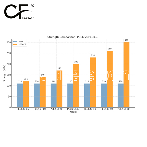
Strength between PEEK and PEEK-CF
PEEK offers good strength with a tensile strength of around 90-100 MPa, while PEEK-CF (carbon fiber reinforced) has significantly higher tensile strength (100-200 MPa) and flexural strength (150-250 MPa), providing greater stiffness and wear resistance. However, PEEK-CF may have slightly lower impact strength due to its brittleness from the carbon fiber reinforcement.

Related Product

Non-stick Easy Demoulding C...

PEEK-CF05 Premium Performan...
Wear-Resistant Heat-Stable ...
Resistance Value 10E6-10E10...
High Temperature Resistant ...
Granular Conductive PEEK CF...


Frequently Asked Questions
Carbon (Xiamen) New Material Co., Ltd. aims to provide buyers with "one-stop" worry-free high-quality services. Here you can find all information about carbon fiber engineering plastics. If you still have questions, please send us an email for consultation!
-
How can I contact the manufacturer of a product that interests me?

When you find a product you are interested in, you can contact the manufacturer directly by sending an email and we will get back to you as soon as possible.
-
How do I find the products that interest me?
All you need to do is enter the keyword, product name in the search window and press the Enter key on your keyboard. Your search results page will then be displayed. You can also search within the product category pages on the home page. Each category is divided into subcategories, allowing you to refine your search and find products that interest you.
-
Where will I find a buying guide?
Please contact our after-sales service directly and we will provide you with a comprehensive operating guide.
-
What are CF Reinforced Thermoplastic Composites?
CF Reinforced Thermoplastic Composites are materials where carbon fibers are incorporated into a thermoplastic matrix. They combine the strength and stiffness of carbon fibers with the processability and recyclability of thermoplastics. For instance, they are used in automotive parts like bumper beams.
-
What are the benefits of CF Reinforced Thermoplastic Composites over traditional composites?
The key benefits include faster production cycles, easier recyclability, and better impact resistance. They also offer design flexibility. An example is in the manufacturing of consumer electronics casings where complex shapes can be achieved more easily.
-
How are CF Reinforced Thermoplastic Composites processed?
Common processing methods include injection molding, extrusion, and compression molding. Injection molding is widely used for mass production. For example, in the production of small components for the medical industry.
-
What industries use CF Reinforced Thermoplastic Composites?
They are utilized in aerospace, automotive, medical, and sports equipment industries. In aerospace, they can be found in interior components. In the medical field, they might be used in prosthetics.
-
How does the carbon fiber content affect the properties of the composites?
Higher carbon fiber content generally leads to increased strength and stiffness but may reduce ductility. A moderate content is often balanced for specific applications. For example, a higher content might be preferred in structural parts of a race car.
-
What are the challenges in using CF Reinforced Thermoplastic Composites?
Challenges include higher material costs, complex processing equipment requirements, and ensuring uniform fiber dispersion. Issues with adhesion between the fibers and the matrix can also arise. An example is in achieving consistent quality in large-scale production.